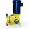
Identifying the Pump Components
Driver – The pump is driven by an AC constant speed motor. Variable speed, pneumatic and hydraulic drivers are also utilized.
The metering pump is a positive displacement chemical dosing device with the ability to vary capacity manually or automatically as process conditions require. It features a high level of repetitive accuracy and is capable of pumping a wide range of chemicals including acids, bases, corrosives or viscous liquids and slurries.
The pumping action is developed by a reciprocating piston which is either in direct contact with the process fluid, or is shielded from the fluid by a diaphragm. Diaphragms are actuated by hydraulic fluid between the piston and the diaphragm. Metering pumps are generally used in applications where one or more of the following conditions exist.
Driver – The pump is driven by an AC constant speed motor. Variable speed, pneumatic and hydraulic drivers are also utilized.

Liquid End – The liquid end design and materials of construction are determined by the service conditions, and the nature of the fluid to be handled. Temperature, flow rate, fluid viscosity, corrosiveness and other factors are considered.

Driver Mechanism – The drive mechanism translates the rotary motion of the driver into reciprocating movement. Industrial duty pumps will submerge this portion of the pump in an oil bath to assure reliability during continuous operation.

Flow Adjustments – Pump flow rate is adjustable by varying stroke length, effective stroke length, or stroking speed. Most metering pumps are supplied with a micrometer screw adjustment similar to the one shown here. The micrometer can also be replaced by an electronic or pneumatic actuator to adjust pump flow rate in response to process signal.


1) The pumping action is developed by a reciprocating piston. This reciprocating motion develops a flow easily represented by a sine wave. Actual flow rate is determined by the formula:
Flow rate = Displacement x Cycles per unit of time

2) Unlike centrifugal pumps, flow rate is not greatly affected by changes in discharge pressure.

3) The metering pump flow vs. stroke characteristic curve is linear, It is not, however necessarily proportional in that 50% stroke setting may not equal 50% flow. This is due to the fact that the calibration line may not pass through 0 on both axes simultaneously. By measuring flow at 2 stroke settings, plotting both points and drawing a straight line through them, other flow rates vs stroke can be accurately predicted. The steady state accuracy of a correctly installed industrial grade metering pump is generally +/- 1.0% or better.
Although a metering pump can generally be adjusted to pump at any flow rate between 0 and its maximum capacity, its accuracy is measured over a range determined by the pump’s turndown ratio.
Most metering pumps have a turndown ratio of 10:1, which simply means that the pump is within its accuracy rating anywhere between 10% and 100% of capacity. Centrac is an example of a new generation metering pump that features higher accuracy and a greater turndown ratio of 100:1. Therefore, this design will accurately dose anywhere between 1% and 100% of capacity.

The liquid end, which is referred to as the wetted part of the pump, is selected to meet the specific service conditions of the application. Required flow and pressure ratings are considered, as well as the physical and chemical properties of the liquid. The liquid end's ability to protect the environment is also a major consideration when dealing with toxic or hazardous chemicals.
All liquid ends have several features in common. First, the liquid is drawn into the wetted end by the rearward motion of a piston, and expelled by the forward motion. To achieve this, the metering pump is supplied with check valves at the suction and discharge connection points. The check valves contain and release the chemical based on system conditions and gravity.
During the suction portion of the stroke, the motion of the piston lifts the suction ball check from its seat allowing liquid into the pump. At the same time, the piston's motion and system back pressure hold the upper check valve (discharge) closed.
This is then reversed during the discharge stroke. Check valves are available in several different designs and configurations. The choice of ball or poppet style is determined by Milton Roy's Engineering department based on capacity of the specific pump.


Most pumps feature either single or double ball configuration as standard. The user can also select single or double ball when the application is better served by one or the other. For example, slurries or liquids with large fibers or particles can cause a single ball to leak if particles are trapped between the ball and seat. Therefore, a double ball check offers more stability and accuracy. On the other hand, since each check valve causes some resistance in the flow path even when open, viscous fluids are better handled with a single ball suction check valve.
Continue with Part ll

